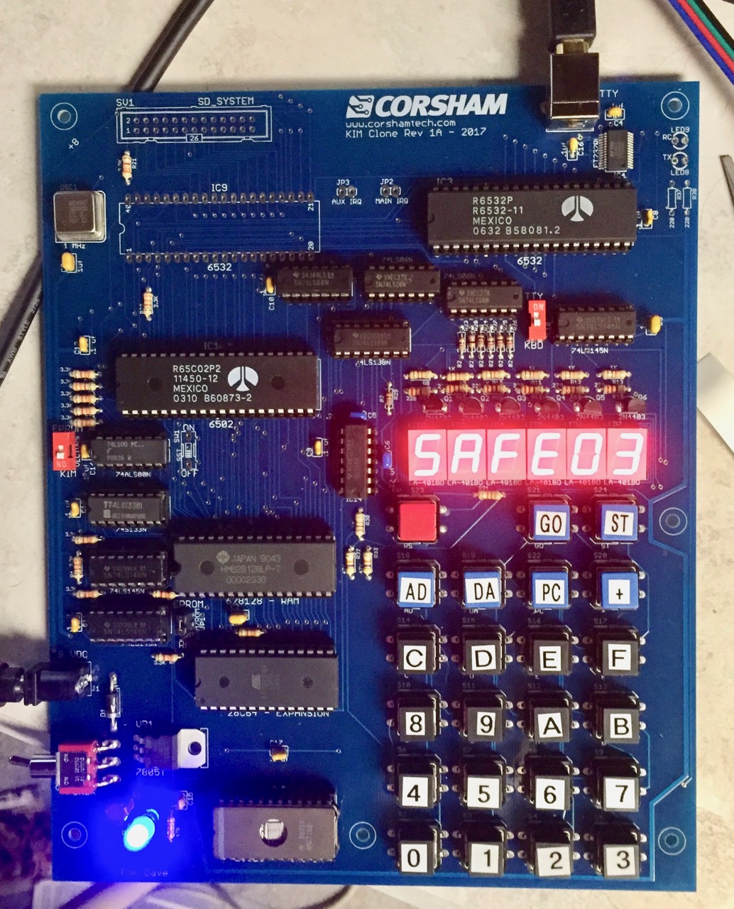
This is the latest set of pictures from this evening. The KIM Clone rev 1A board is functional and fun to play with! I had Lunar Lander from The First Book of KIM loading, which explains the “SAFE 03” message (I landed my spaceship at a speed of 3). The connector labeled “SD SYSTEM” and U9 are for connecting one of our SD Card Systems. Paper tape and cassette storage was state-of-the-art in the 70s, but now we can use a micro SD to save/load programs to the KIM Clone.
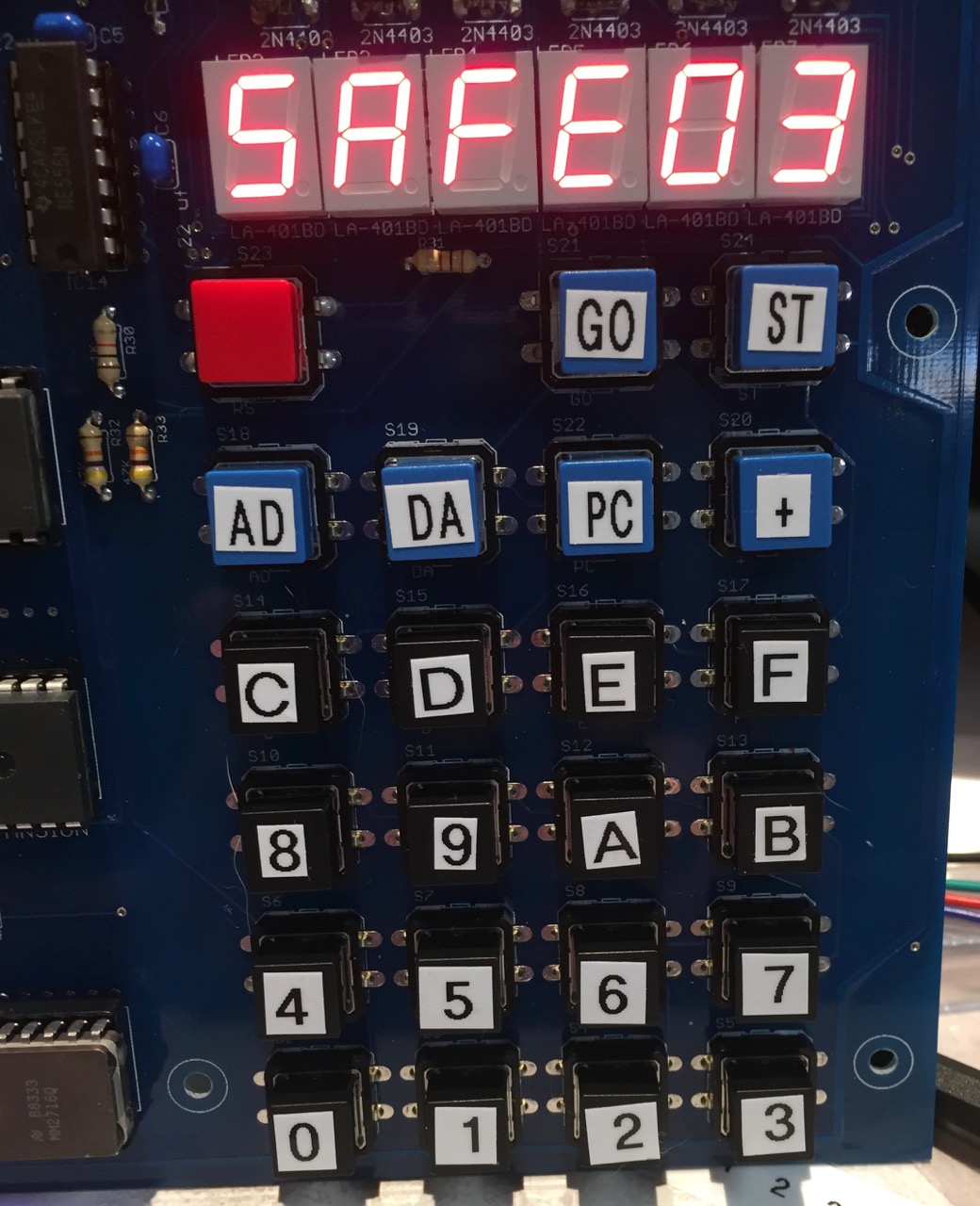
Here are some more detailed photos of specific parts. First is the display and keypad. Those are real keycaps and the keys “click” when you press them so there is tactile feedback when you press a button. The labels on the keycaps aren’t quite good enough but I priced getting custom labels done and it was a $600 investment. For labels. Right now I’m looking at other options. Oh, the big red button is RESET.
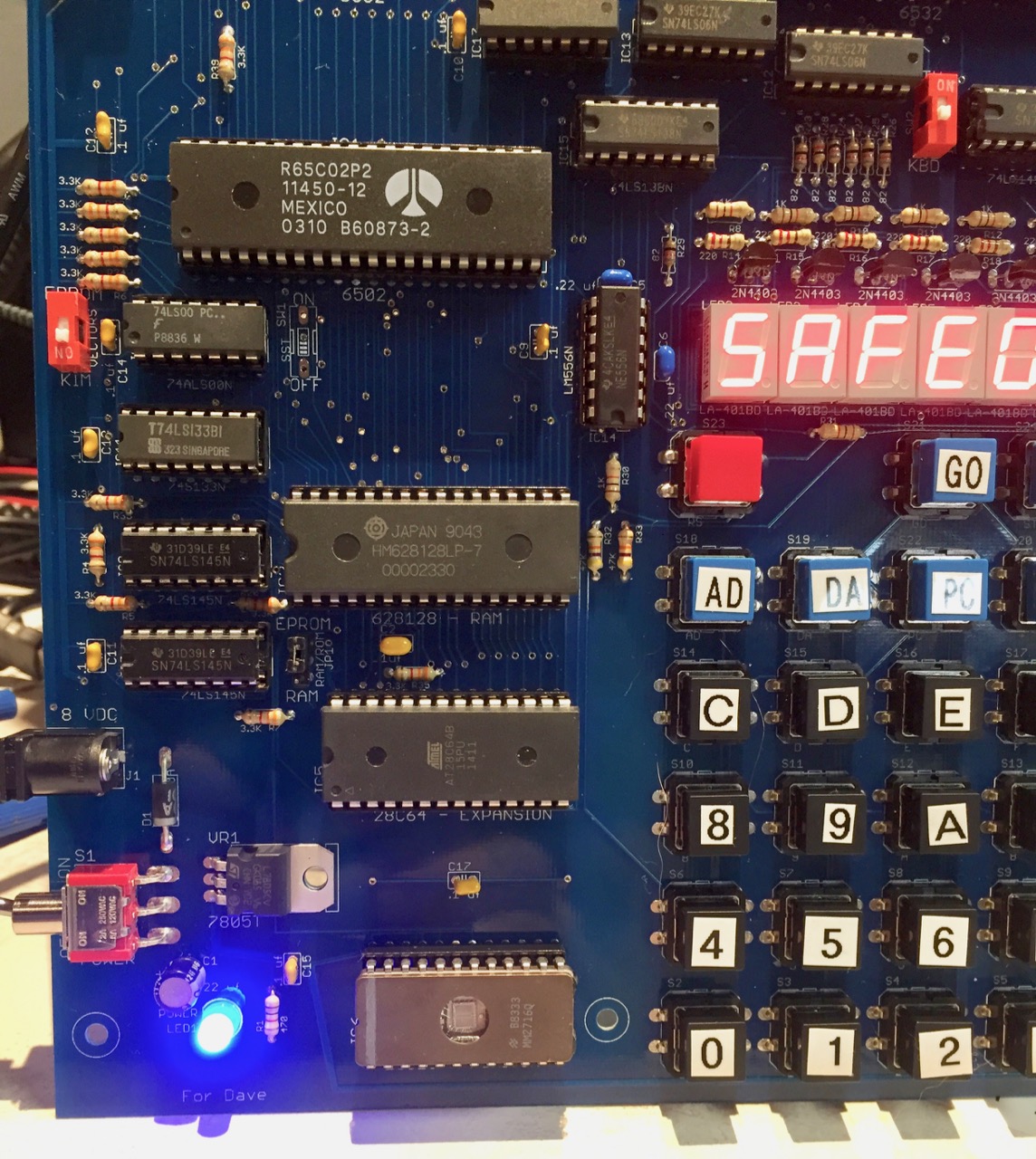
The board can take either a 6502 or 65C02. Not sure which I’ll include, but probably the C02. Beneath it is the RAM, the expansion EEPROM and the KIM monitor EPROM. On the left are the power plug and power switch. The system will include the power supply, and it’s rated for 110-220 VAC so it’ll work in most other countries. You can see the SST switch is missing; testing single-step is on the to-do list for this weekend. The expansion EEPROM resides from E000 to FFFF and can be displayed and replaced with RAM. The monitor EPROM contains the modified KIM monitor that resides from 1800 to 1FFF. Either of these EPROMs can be replaced with user-supplied code. The board has a lot of discrete 7400 series parts; a future version might go with a CPLD which can also offer some interesting memory management options. The RAM is 128K but only the bottom 64K is used for now.
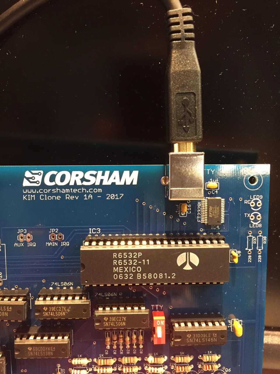
There is a USB “B” connector on the top for connection to a PC/Mac/whatever for use as a console. I should probably solder in the two resistors and LEDs that indicate serial port activity. The interface chip is a high quality FTDI part, not one of those “Horrific” chips. The interface is powered from the USB port so the serial port doesn’t go away when the board is powered off. I’m considering going to a micro USB connector but this is working so that eliminates more unknowns for the next spin.
The first public showing won’t be until VCF East in the spring of 2018. I can’t make VCF MW this year. A few people have suggested some additions, and I want to move some of the LEDs around a bit so there will be at least one more revision of the board before it’s ready for sale.