There were several errors on the Rev 4 SS-50 motherboards that prevent them from using interrupts in most cases. This doesn’t affect most Flex users because Flex uses polled I/O, but this can prevent NitrOS-9 from running since it uses interrupts for several features. There is a modification to fix the problem; once this is done, the motherboard is technically a revision 4A motherboard. As of now, there is no revision 5 with all the fixes applied.
What’s Wrong
Basically, three of the pull-up resistor values are too small, making it impossible for some chips to pull the interrupt lines low. This affects /FIRQ, /IRQ and /NMI. The other problem is that one of those lines wasn’t attached to the resistor at all.
How to Fix It
On the Rev 4 motherboard, RN1 is a resistor network of 680 ohms each. This device needs to be removed, five of the resistors replaced with 680 ohm resistors, and three replaced with 6.8K ohm resistors. There is also a short jumper to install on the bottom of the board.
What You’ll Need
- Soldering iron, solder sucker, solder, etc. Basic tools for circuit board work.
- Five 680 ohm resistors, 1/4 or 1/8 watt.
- Three 6800 ohm resistors, 1/4 or 1/8 watt.
- Short piece of fine wire, such as wire wrap wire, about 1.5″ long, ends stripped.
Removing RN1
This is the worst part of the job. Personally, I use sharp wire cutters to cut the network into smaller pieces, mount the board in a vise, then use needle nose pliers and a soldering iron to heat one piece at a time and pull it out. Then the holes need to have the solder sucked out. This is the longest part of the job.
If you follow this method, make the cuts vertically so each resistor piece is broken away from the others, as this will leave something to grab onto when heating up the solder on the other side.
New Resistors
Refer to this picture:
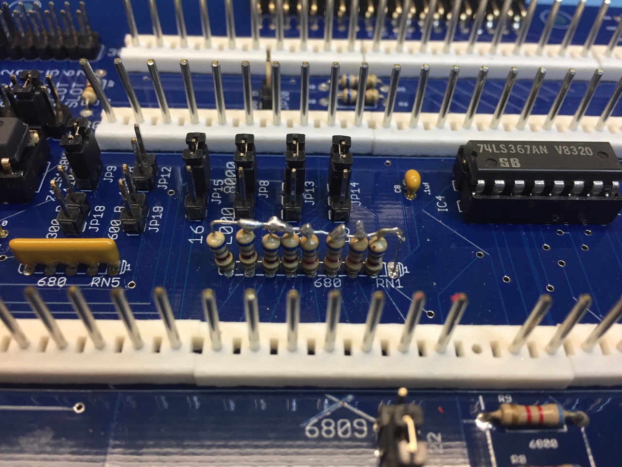
Going from the left-most position, the resistors are 680, 680, 680, 680, 6800, 6800, 6800, 680. Ie, four 680 in a row, then three 6800, then one more 680.
Solder each resistor vertically in place, leaving the long lead on the top. Once all are in, bend the right-most top pin and insert it into the first position. Solder that in place. Now just bend the leftmost top lead over, solder all the top leads to the one going back to the first position. I’m sure my description isn’t good, but the picture should explain it.
Cut
Again, refer to the picture above and cut the trace just above the “6809” silkscreen that goes to JP22.
Jumper
On the bottom of the board you’ll need to solder one short jumper:
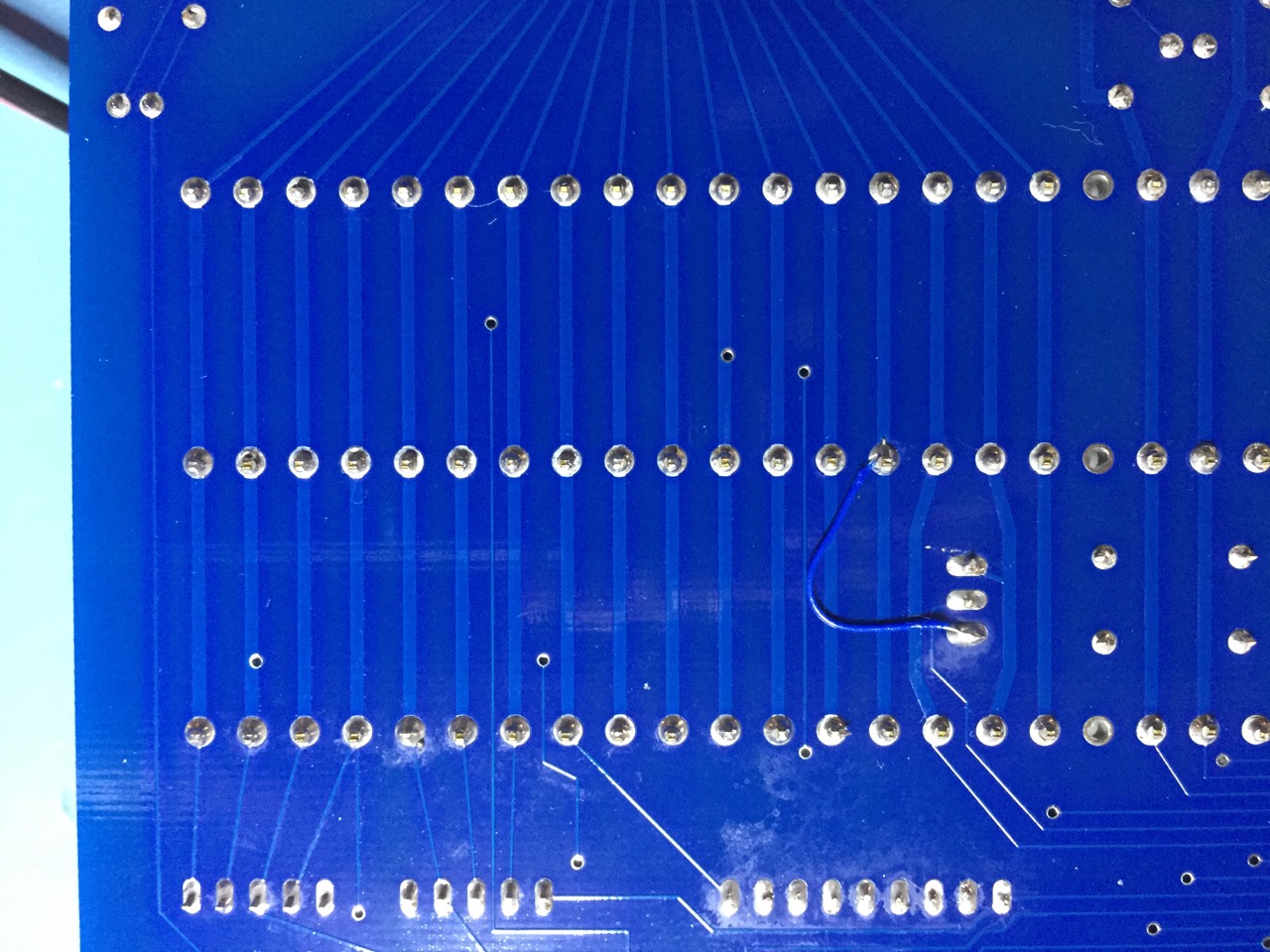
That’s JP22. Rather than trying to describe where the jumper goes, it’s easier to just look at the picture.
I Can’t Do That (Or Don’t Want To)
Okay, we know many customers do not want to make these changes, so I’m offering to do the changes free of charge if you mail your motherboard to me. In most cases I can make the changes in a night or two and mail it back. Please email me before mailing your board back.
The Rev 5 motherboard will fix all these issues but there is no definite estimate on when I’ll re-spin it. There is another very large project in the queue that I’d like to finish by mid-summer.